Introduction
How much water can a culvert carry? It depends on how high the water may rise at the inlet, the headwater. The FHWA method in HDS-5 works out the headwater twice: once for the inlet as the bottleneck and once for the barrel and outlet. The higher of the two controls. A 36 in concrete pipe with a square-edged headwall needs 3.99 ft of headwater to pass 50 ft³/s, so inlet control governs there.
This calculator gives the inlet-control and outlet-control headwater for a flow, or the largest flow for an allowable headwater. It covers circular concrete pipes and rectangular concrete boxes with the standard HDS-5 inlets. It also reports the barrel velocity, the critical depth and the Manning full-flow capacity. It is for civil and highway engineers, drainage designers and reviewers checking a culvert under a road or driveway.
Formulas
Inlet control, HDS-5 Appendix A, with D in ft and Q in ft³/s:
unsubmerged (Q/AD^0.5 ≤ 3.5):  HW/D = Hc/D + K (Q / A D^0.5)^M − 0.5 S
submerged   (Q/AD^0.5 ≥ 4.0):  HW/D = c (Q / A D^0.5)² + Y − 0.5 S
Outlet control with the barrel flowing full, HDS-5 chapter 3:
H = [1 + ke + 29 n² L / R^1.33] × V² / 2g
HW = H + h_o − L S, h_o = max(TW, (d_c + D) / 2)- D — pipe diameter or box rise; A — full barrel area; S — barrel slope
- Hc — specific head at critical depth, d_c + V_c²/2g; between 3.5 and 4.0 the result is interpolated
- K, M, c, Y — inlet constants of HDS-5 Table A.1; ke — entrance loss coefficient of Table C.2
- n — Manning roughness; L — barrel length; R — hydraulic radius; V = Q / A
- TW — tailwater depth above the outlet invert; d_c — critical depth
| Inlet | K | M | c | Y | ke |
|---|---|---|---|---|---|
| Pipe, square edge with headwall | 0.0098 | 2.0 | 0.0398 | 0.67 | 0.5 |
| Pipe, groove end with headwall | 0.0018 | 2.0 | 0.0292 | 0.74 | 0.2 |
| Pipe, groove end projecting | 0.0045 | 2.0 | 0.0317 | 0.69 | 0.2 |
| Box, wingwalls 30° to 75° | 0.026 | 1.0 | 0.0347 | 0.81 | 0.4 |
| Box, wingwalls 90° or 15° | 0.061 | 0.75 | 0.0400 | 0.80 | 0.5 |
| Box, wingwalls 0° | 0.061 | 0.75 | 0.0423 | 0.82 | 0.7 |
Assumptions and limitations
- One concrete barrel with a standard inlet. Corrugated metal, tapered inlets, skewed or blocked culverts and several barrels side by side are not covered.
- The inlet equations are fits to laboratory tests. They agree with the HDS-5 nomographs within a few per cent up to a headwater of about three diameters.
- The outlet method assumes a full barrel. With a part-full barrel and low headwater it is only approximate, and a water-surface profile gives the exact answer.
- Headwater is measured from the inlet invert. The approach velocity in the stream is neglected, which is slightly conservative.
- Manning's n for concrete culverts is 0.011 to 0.013. The full-flow Manning capacity is a reference only; the headwater sets the real capacity.
Worked example
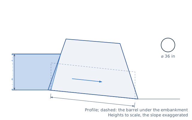
A 36 in concrete pipe with a square-edged headwall is 100 ft long on a 1 % slope, with n = 0.012 and no tailwater. What headwater does a flow of 50 ft³/s need?
- Barrel area: π × 3² / 4 = 7.07 ft²; barrel velocity 50 / 7.07 = 7.07 ft/s.
- Discharge index: 50 / (7.07 × 3^0.5) = 4.08, so the inlet is submerged.
- Inlet control: HW/D = 0.0398 × 4.08² + 0.67 − 0.5 × 0.01 = 1.33, so HW = 3.99 ft.
- Outlet losses: H = (1 + 0.5 + 29 × 0.012² × 100 / 0.75^1.33) × 7.07² / 64.3 = 1.64 ft.
- Critical depth 2.30 ft, so h_o = (2.30 + 3) / 2 = 2.65 ft.
- Outlet control: HW = 1.64 + 2.65 − 100 × 0.01 = 3.29 ft.
Inlet control governs at 3.99 ft. A groove-end pipe would need only 3.67 ft. The barrel alone could carry 72 ft³/s flowing full at this slope, which shows how much the inlet limits it.
FAQ
What is the difference between inlet and outlet control?
Under inlet control the entrance is the bottleneck, so only a better inlet helps. Under outlet control the barrel friction, length and tailwater set the headwater.
How much flow does a 36 in culvert carry?
With a square-edged headwall, 100 ft long on 1 %, it passes 56 ft³/s at a headwater of 4.5 ft, 1.5 diameters. A groove end raises that to 63 ft³/s.
What headwater is allowed at a culvert?
The road owner sets it, often as a ratio HW/D or as a freeboard below the road edge. The calculator finds the flow for any limit you enter.
Why is the Manning capacity higher than the culvert capacity?
Manning assumes a long, full pipe with no entrance. A short culvert usually loses more head at the inlet than in the barrel.
What does tailwater do?
High tailwater pushes the outlet-control headwater up. With 4 ft of tailwater the same 36 in pipe needs 4.64 ft of headwater at 50 ft³/s, now under outlet control.
What entrance loss coefficient should I use?
HDS-5 Table C.2 gives 0.5 for a square-edged headwall, 0.2 for a groove end and 0.4 to 0.7 for boxes depending on the wingwalls.
Related calculators
- Open-channel flow (Manning) — tailwater depth in the channel below the culvert.
- Rational-method runoff — the design flow from the catchment.
- Drain pipe size calculator (Manning) — gravity pipes flowing part full.
- Weir and flume flow calculator — measuring stream flow with a weir or flume.