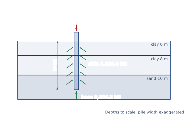
Axial capacity of a single driven or bored pile in layered clay and sand: shaft friction by the α and β methods plus end bearing, with a factor of safety.
Drawn for the default inputs. It redraws as you change them.
Results are estimates. They do not replace the governing code, class or flag requirements, or a check by a competent person. Report a problem
Introduction
A pile carries its load in two ways: friction along its shaft and bearing under its tip. In clay the shaft friction is a fraction α of the undrained shear strength. In sand it is a fraction β of the effective vertical stress. The tip bears a multiple of the soil strength or stress. A 610 mm steel pipe pile driven 20 m through soft and firm clay into dense sand has an ultimate capacity of about 3 729 kN.
This calculator adds up the shaft friction layer by layer and the end bearing at the tip, then divides by a factor of safety. Driven piles use the API RP 2GEO method, and bored piles the FHWA method of O'Neill and Reese. It is for geotechnical and structural engineers making a first estimate, and for students checking hand calculations.
clay:  f = 0.55 s_u, none in the top 1.5 m and the bottom D;  q_b = 6 (1 + 0.2 L/D) s_u ≤ 9 s_u
sand:  f = β σ'v ≤ 200 kPa,  β = 1.5 − 0.245 √z  (0.25 to 1.2, z in m);  q_b = 57.5 N60 kPa
P — pile perimeter; A_b — base area; D — diameter; L — embedded length
API RP 2GEO is written for open- and closed-end pipe piles driven offshore. The page assumes the pile acts plugged, with end bearing on its full area.
Sand layers take an SPT N60. Its relative density sets the API β and N_q. API gives no values for loose sand, so such layers are refused for driven piles.
Only the soil's capacity is computed. Pile weight, downdrag, group effects, settlement and the structural strength of the pile need separate checks.
These are design methods for a first estimate. Load tests or dynamic monitoring usually confirm the capacity on a real project.
Worked example
A closed-end steel pipe pile of 610 mm diameter is driven 20 m. The soil is 6 m of soft clay (s_u 40 kPa, γ' 8 kN/m³), 8 m of firm clay (s_u 80 kPa, γ' 9 kN/m³) and then dense sand with N60 = 35 (γ' 10 kN/m³). Use FS = 2.5.
Effective stress: 48 kPa at 6 m, 120 kPa at 14 m and 180 kPa at the tip.
Soft clay: ψ = 40/σ'v, so α rises from 0 at the surface to 0.55 at 6 m. Integrating f = α s_u gives 100.97 kN per metre of perimeter.
Firm clay: in the same way, 332.67 kN per metre.
Dense sand: f = 0.46 × σ'v, with an average stress of 150 kPa over 6 m, gives 414.0 kN per metre.
Shaft friction: 847.6 × π × 0.61 = 1 624 kN.
End bearing: q_b = 40 × 180 = 7 200 kPa on 0.2922 m², so 2 104 kN.
Bored instead, the same pile would carry about 1 701 kN in shaft friction but only 588 kN at the base.
The worked example, drawn by the same code as the live drawing above.
FAQ
How do you calculate pile capacity?
Add the shaft friction of every layer the pile passes through to the end bearing at the tip. Divide the sum by a factor of safety, usually 2 to 3, for the allowable load.
What is the α method?
A total-stress method for clay. The unit shaft friction is α times the undrained shear strength; α falls from 1 in soft clay to about 0.3 to 0.5 in stiff clay.
What is the β method?
An effective-stress method. The unit shaft friction is β times the effective vertical stress, with β combining the earth pressure coefficient and the friction angle at the pile wall.
Why do driven and bored piles have different capacities?
Driving displaces and densifies the soil around the pile. Boring removes soil and loosens the walls, so a bored pile has lower base resistance for the same size.
Why is there no shaft friction near the top of a bored pile in clay?
The clay there shrinks, cracks and may be disturbed by construction. O'Neill and Reese ignore the top 1.5 m and the bottom one diameter.
What factor of safety should I use?
Traditional practice uses 2 to 3, the lower values only when load tests confirm the capacity. Follow the governing code; LRFD codes use resistance factors instead.
Before every release the calculator must reproduce each case below. The note under each case says where the expected answer comes from: a standard, a textbook, a published table, or a hand calculation shown in full.
API α: ψ = 0.25 gives α = 1.0 (cap), ψ = 1 gives 0.5, ψ = 4 gives 0.354; a uniform clay with s_u = σ'v has f = 0.5 s_uAPI RP 2GEO (2011) 8.1: α = 0.5 ψ^−0.5 for ψ ≤ 1, 0.5 ψ^−0.25 for ψ > 1, α ≤ 1
API Table 1: dense sand β 0.46, f_lim 96 kPa, N_q 40, q_lim 10 MPa; N60 35 is dense, 20 medium dense, 60 very dense; loose sand is refused for driven pilesAPI RP 2GEO (2011) Table 1; Terzaghi, Peck and Mesri (1996) relative density by SPT N
Worked example, driven 610 mm pipe pile, 20 m: shaft 100.97 + 332.67 + 414.0 = 847.6 kN/m × π × 0.61 = 1 624 kN; tip 40 × 180 = 7 200 kPa × 0.2922 m² = 2 104 kNHand integration of the API α and β formulas over each layer (closed-form integrals of z^0.25 and z^0.5 terms)
Bored pile in clay (s_u 60 kPa, D 1 m, L 15 m): f = 0.55 × 60 = 33 kPa over 1.5–14 m = 1 296 kN; N_c = 9, base 540 kPa × 0.785 = 424 kNO'Neill & Reese (1999) FHWA-IF-99-025: α = 0.55, top 1.5 m and bottom D excluded, N_c = 6 (1 + 0.2 L/D) ≤ 9
Bored pile in sand (N60 30, γ' 10, D 1 m, L 10 m): β = 1.5 − 0.245 √z ≤ 1.2, f = β σ'v integrated by hand; base 57.5 × 30 = 1 725 kPa; N60 10 scales β by 10/15O'Neill & Reese (1999): β method for cohesionless soil and q_b = 0.6 N60 tsf (57.5 N60 kPa) ≤ 30 tsf
US units give the same capacity as SI; layers ending above the tip, bad lines, stiff clay for bored piles and a word for N60 in bored sand are refusedBehaviour check: warnings and rejected inputs
Worked example of the article: the calculator reproduces 1 624 kN, 2 104 kN, 3 729 kN, 1 491 kN to the digits printedThe worked example on this page, to the digits printed
Assumptions and sources
Assumptions and limits
Driven piles follow API RP 2GEO: the α method in clay and the β method with the Table 1 limits in sand and silt, by relative density. API gives no values for loose sand, so a loose layer is refused for driven piles. The pile is assumed plugged, with end bearing on its full area.
Bored piles (drilled shafts) follow O'Neill and Reese (FHWA, 1999): α = 0.55 in clay with no friction in the top 1.5 m and the bottom one diameter, β = 1.5 − 0.245 √z in sand, and end bearing from N60 in sand.
Sand and silt layers take an SPT N60 value, from which the relative density follows Terzaghi and Peck; driven piles also accept the words medium dense, dense or very dense. Use effective (submerged) unit weights below the water table.
The capacity is geotechnical only: the pile weight, negative skin friction, group effects, settlement and the strength of the pile itself are not checked.
The allowable load is the ultimate capacity divided by one factor of safety, commonly 2 to 3; LRFD design uses resistance factors instead, and load tests can justify lower factors.
Sources
API RP 2GEO (2011, Addendum 1 2014), Geotechnical and Foundation Design Considerations, section 8.1 (α method for cohesive soils) and Table 1 (design parameters for cohesionless siliceous soil)
O'Neill, M.W. and Reese, L.C. (1999), Drilled Shafts: Construction Procedures and Design Methods, FHWA-IF-99-025 (side and base resistance in cohesive and cohesionless soils)
Terzaghi, K., Peck, R.B. and Mesri, G. (1996), Soil Mechanics in Engineering Practice, 3rd ed., Wiley (relative density from the SPT N value)
Cite this calculator
Papandreou, C. (2026). Pile capacity calculator (driven and bored piles). Engineering Bible. https://engineeringbible.com/civil/pile-capacity/
Embed this calculator on your site
Copy this HTML into your page. The calculator stays free to use and links back here.