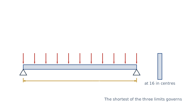
Drawn for the default inputs. It redraws as you change them.
Results are estimates. They do not replace the governing code, class or flag requirements, or a check by a competent person. Report a problem
Introduction
How far can a joist span? Far enough that its bending stress stays below the allowable value and its sag stays within the deflection limits. Both follow from simple beam theory once the load per joist, the section properties and the wood's strength and stiffness are known. A Douglas Fir-Larch No. 2 2×10 at 16 in centres, with 10 psf dead and 40 psf live load, can span 15.61 ft, limited by bending.
This calculator computes the maximum span of a rectangular joist or rafter from mechanics, not from code span tables. It applies the NDS load duration, size and repetitive member factors, checks bending and the live and total load deflection limits, and says which one governs. It also checks a span you enter. It is for builders, designers, engineers and students sizing floor joists, ceiling joists and rafters.
Formulas
Load per joist and section properties:
w = q × s, S = b d² / 6, I = b d³ / 12
Span limited by bending, with F'b = Fb × C_D × C_F × C_r:
M = w L² / 8 ≤ F'b S → L_b = √( 8 F'b S / w )
Span limited by deflection, with the limit L/n:
Δ = 5 w L⁴ / (384 E I) ≤ L / n → L_Δ = ( 384 E I / (5 w n) )^(1/3)
q — load per unit floor area; s — joist spacing; b, d — actual width and depth
C_D — load duration, 1.0 for occupancy live load; C_F — size factor; C_r = 1.15 for joists at 24 in or less
Live load deflection uses the live load only; total load deflection uses dead plus live
Assumptions and limitations
The joist is simply supported and uniformly loaded. Continuous joists, point loads and openings need a full analysis.
The compression edge is held by the floor or roof sheathing, the wood is dry in service and at normal temperature.
Shear, bearing, notches and floor vibration are not checked. Long, shallow joists can feel bouncy even when they meet L/360.
The spans come from mechanics with the NDS factors. Code span tables are built in a similar way but may round or add checks, so small differences are normal.
Worked example
A floor has Douglas Fir-Larch No. 2 2×10 joists (1.5 × 9.25 in) at 16 in centres. The dead load is 10 psf and the live load 40 psf. Use L/360 for live and L/240 for total load deflection.
Load per joist: 50 psf × 16/12 ft = 66.67 lb/ft, or 5.556 lb/in. The live part is 4.444 lb/in.
Section: S = 1.5 × 9.25² / 6 = 21.39 in³ and I = 1.5 × 9.25³ / 12 = 98.93 in⁴.
Bending: L = √(8 × 1 138.5 × 21.39 / 5.556) = 187.3 in, or 15.61 ft.
Live load deflection: L = (384 × 1 600 000 × 98.93 / (5 × 4.444 × 360))^(1/3) = 196.6 in, or 16.38 ft.
Total load deflection at L/240: 17.41 ft.
Bending governs, so the maximum span is 15.61 ft, or 15 ft 7 in.
The worked example, drawn by the same code as the live drawing above.
FAQ
How far can a 2×10 joist span?
It depends on the species, grade, spacing and loads. A Douglas Fir-Larch No. 2 2×10 at 16 in with 40 psf live and 10 psf dead load spans about 15.6 ft by this method.
What is the difference between L/360 and L/240?
L/360 limits the live load deflection of floors so finishes do not crack. L/240 limits the total deflection under dead plus live load.
Why does the size factor change with depth?
Deeper lumber has a lower bending strength per unit area, because large members contain more and larger defects. The NDS raises Fb for small sizes, by 1.1 for a 2×10 and 1.5 for a 2×4.
What is the repetitive member factor?
A 15 % increase in bending stress for joists, rafters and studs spaced 24 in or less, when three or more share the load through sheathing. A weak joist is helped by its neighbours.
Does this work for rafters?
Yes, using the horizontal span and loads per horizontal area. Use C_D = 1.15 when snow is the live load.
Can I use metric timber grades such as C24?
Choose "Other" and enter the bending stress and modulus. Eurocode 5 designs with partial factors and different load factors, so the result is only an estimate for EN 338 grades.
Before every release the calculator must reproduce each case below. The note under each case says where the expected answer comes from: a standard, a textbook, a published table, or a hand calculation shown in full.
DF-L No. 2 2×10 at 16 in, 10 + 40 psf: F'b = 900 × 1.1 × 1.15 = 1 138.5 psi; bending span √(8 × 1 138.5 × 21.39 / 5.556) = 187.3 in = 15.61 ft governsHand calculation in inch-pound units: S = 1.5 × 9.25²/6, w = 50 psf × 16/12 ft = 66.67 lb/ft; NDS 2018 C_F = 1.1 and C_r = 1.15
Deflection spans of the same joist: L/360 under 40 psf gives (384 × 1.6e6 × 98.93 / (5 × 4.444 × 360))^⅓ = 196.6 in; L/240 under 50 psf gives 208.9 inΔ = 5 w L⁴ / (384 E I) solved for L; I = 1.5 × 9.25³/12 = 98.93 in⁴
NDS size factors for 2 in lumber: 2×4 1.5, 2×6 1.3, 2×8 1.2, 2×10 1.1, 2×12 1.0, 2×14 0.9; C_r drops to 1.0 beyond 24 in spacingAWC NDS Supplement 2018, Table 4A size factors (2" and 3" thick); NDS 4.3.9 repetitive member factor
Heavy dead load: with 60 psf dead and 5 psf live, dead alone at C_D 0.9 governs bending (60/65 > 0.9/1.0)NDS 2018 2.3.2: each load combination is checked with the C_D of its shortest-duration load
Span check at 15 ft: stress ratio (15/15.606)² = 92.4 %; live deflection 0.384 in (L/469); a flat member, thick preset lumber and no load are refusedBehaviour check: warnings and rejected inputs
Worked example of the article: the calculator reproduces 1 139 psi, 15.61 ft, 16.38 ft, 17.41 ft, 15.61 ft to the digits printedThe worked example on this page, to the digits printed
Assumptions and sources
Assumptions and limits
Spans are computed from mechanics for a simply supported member under uniform load: M = wL²/8 and Δ = 5wL⁴/(384EI). They are not copied from code span tables, which may include other checks and rounding.
Allowable bending stress F'b = Fb × C_D × C_F × C_r by the NDS: dry service, normal temperature, the compression edge held by sheathing (C_L = 1) and C_r = 1.15 for joists at 24 in or less with at least three members sharing the load.
The dead load is also checked alone with C_D = 0.9. Shear, bearing at the supports, vibration and notches are not checked; shear rarely governs uniformly loaded joists of usual spans.
Loads are area loads on plan for floors; for a sloping rafter enter the horizontal projection of the span and loads per horizontal area. Self-weight belongs in the dead load.
The preset grades use NDS Supplement Table 4A reference values for 2 in thick dimension lumber, with C_F from the depth; other species, grades or sizes take Fb, E and C_F as entered.
Sources
AWC National Design Specification (NDS) for Wood Construction, 2018 ed., 4.3 adjustment factors (C_D Table 2.3.2, C_F, C_r 4.3.9) and 3.3 bending members
AWC NDS Supplement, Design Values for Wood Construction, 2018 ed., Table 1B (section properties of standard dressed lumber) and Table 4A (reference values and size factors)
Gere, J.M. and Goodno, B.J., Mechanics of Materials, Cengage (simply supported beam under uniform load: M = wL²/8, Δ = 5wL⁴/384EI)
Cite this calculator
Papandreou, C. (2026). Joist span calculator (bending and deflection). Engineering Bible. https://engineeringbible.com/structural/joist-span/
Embed this calculator on your site
Copy this HTML into your page. The calculator stays free to use and links back here.