Introduction
Mechanical advantage is the ratio of the load a machine lifts to the effort you apply. The ideal value is the ratio of the distances the effort and the load move. Friction makes the actual value smaller. A crowbar with a 1.5 m handle and the load 0.3 m from the fulcrum multiplies your force by 5, so 1 280 N moves a 6.4 kN load.
This calculator covers the five classic machines: levers of all three classes, pulley blocks, the inclined plane, the screw jack and the wheel and axle. It gives the ideal and actual mechanical advantage, the effort force and the efficiency, and for a screw jack the raising and lowering torques with thread and collar friction. It is for students, technicians and anyone planning a lift.
Formulas
Ideal mechanical advantage (distance ratio) and actual mechanical advantage:
AMA = W / F, efficiency η = AMA / IMALever, pulley block, wheel and axle:
lever:   IMA = a_e / a_l,   F = W a_l / a_e
pulley:  IMA = n,           F = W / (η n)
winch:   IMA = R / r,       F = W / (η R / r)
Inclined plane, effort along the slope:
IMA = 1 / sin θ, F = W (sin θ + μ cos θ)Screw jack (Shigley eqs. 8-1, 8-5, 8-6):
T_R = (W d_m / 2) (l + π μ d_m sec α) / (π d_m − μ l sec α) + W μ_c d_c / 2
T_L = (W d_m / 2) (π μ d_m sec α − l) / (π d_m + μ l sec α) + W μ_c d_c / 2
IMA = 2π R / l, F = T_R / R- W — load; F — effort; a_e, a_l — effort and load arms from the fulcrum
- n — rope parts supporting the moving block; R, r — wheel and axle radii
- θ — slope angle; μ — friction coefficient on the slope or thread
- d_m — mean thread diameter; l — lead; α — thread flank half-angle (0° square, 14.5° Acme)
- μ_c, d_c — collar friction and mean collar diameter; R — handle radius for the screw jack
Assumptions and limitations
- The load moves slowly at steady speed, so inertia is ignored. The effort is the force that just keeps it moving upward.
- Levers are rigid with a frictionless fulcrum, so their actual and ideal advantage are equal.
- For a pulley block, enter the overall efficiency of the block. It falls as more sheaves are added.
- The screw jack follows Shigley's power-screw equations. The thread is self-locking when the thread term of T_L is positive.
- These are statics results. Lifting gear also needs its rated load, a safety factor and an inspection.
Worked example
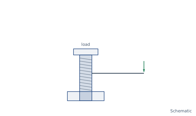
A screw jack has a square thread of 32 mm major diameter, 4 mm pitch and two starts, so d_m = 30 mm and the lead is 8 mm. It lifts 6.4 kN. Thread and collar friction are both 0.08, the collar mean diameter is 40 mm, and the handle radius is 300 mm. These are the data of Shigley Example 8-1.
- Thread torque to raise: 96 × (8 + 7.54) / (94.25 − 0.64) = 15.94 N·m.
- Collar torque: 6 400 × 0.08 × 0.040 / 2 = 10.24 N·m, so the raising torque is 26.18 N·m.
- Lowering torque: −0.466 + 10.24 = 9.77 N·m. The thread alone would run down, but the collar holds the load.
- Effort at the handle: 26.18 / 0.300 = 87.3 N.
- IMA = 2π × 300 / 8 = 235.6; AMA = 6 400 / 87.3 = 73.3; efficiency 31.1 %.
More than two-thirds of the effort goes into friction, and the collar friction is what stops the jack running down.
FAQ
What is the difference between ideal and actual mechanical advantage?
The ideal value assumes no friction and is the ratio of distances moved. The actual value is load over effort, and is smaller because of friction.
What are the three classes of lever?
Class 1 has the fulcrum between load and effort, like a crowbar. Class 2 has the load in the middle, like a wheelbarrow. Class 3 has the effort in the middle, like tweezers, and always needs more effort than the load.
How do I find the mechanical advantage of a pulley system?
Count the rope parts that hold up the moving block. Four parts give an ideal advantage of 4; friction in the sheaves reduces the actual value.
Why is a screw jack self-locking?
When the friction torque on the thread exceeds the torque the load creates through the thread's lead, the load cannot turn the screw. A small lead and a high friction coefficient make a screw self-locking.
What efficiency does a screw jack have?
The jack in the example has 31 %. A ball thrust bearing at the collar raises it; a ball screw raises it much further but is not self-locking.
Does an inclined plane save work?
No. It lowers the force but lengthens the distance, and friction adds work. The ideal advantage is the slope length over the height.
Related calculators
- Torque, power and speed — power to drive a winch or screw.
- Gear ratio, rpm and torque — mechanical advantage of gear trains.
- Bolt torque and preload — another screw under friction.
- Lifting sling and wire rope load — loads in slings and rigging.