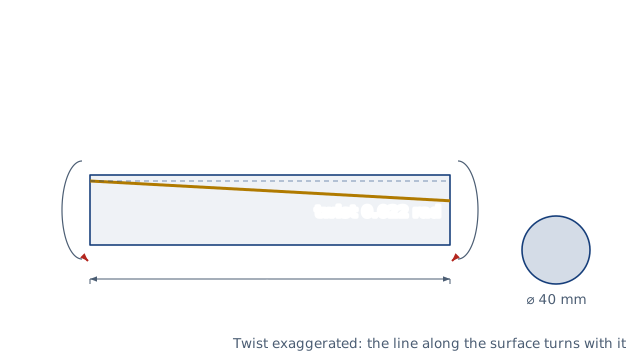
Shear stress and angle of twist of solid and hollow round shafts, the torque they can carry, the diameter for an allowable stress or twist, and power to torque.
Drawn for the default inputs. It redraws as you change them.
Results are estimates. They do not replace the governing code, class or flag requirements, or a check by a competent person. Report a problem
Introduction
A shaft that transmits torque twists, and the shear stress in it grows from zero at the centre to a maximum at the surface. For a solid round shaft the surface stress is 16 T / (π d³). A 40 mm steel bar carrying 340 N·m sees 27 MPa and twists 1.26 degrees over 1.3 m.
This calculator checks a solid or hollow shaft for shear stress and angle of twist, and gives the largest torque it can carry within your limits. It can also size the shaft: the diameter needed for an allowable stress, an allowable twist, or both. Torque can be entered directly or from power and speed. It is for engineers and students designing drive shafts, couplings, spindles and torsion bars.
Formulas
J = π (d_o⁴ − d_i⁴) / 32
τ = T r / J = 16 T / (π d_o³ (1 − k⁴)),    k = d_i / d_o
θ = T L / (G J)
T = P / ω = 9 549 P[kW] / n[rpm]    N·m
Allowable torque and required diameter:
T_τ = τ_allow J / r,    T_θ = θ_allow G J / L
d_τ = [16 T / (π τ_allow (1 − k⁴))]^(1/3)
d_θ = [32 T L / (π G θ_allow (1 − k⁴))]^(1/4)
T — torque; d_o, d_i — outside and inside diameters; r = d_o/2
L — length between the torques; G — shear modulus (81 GPa for steel, 27 GPa for aluminium)
θ — angle of twist in radians; τ_allow, θ_allow — the limits you set
Assumptions and limitations
The shaft is straight, round and uniform, and stays elastic. Plane sections remain plane and the stress grows linearly with radius.
Keyways, splines, shoulders and holes raise the local stress. Apply a stress-concentration factor or a code allowable that includes one.
Only torsion is checked. Most shafts also bend, which needs a combined stress check, and varying torque needs a fatigue check.
Torque from power assumes steady running. Starting torque, shock loads and torsional vibration can be much higher.
A twist limit per metre is entered as the allowable angle with a length of 1 m.
Worked example
A solid steel bar 40 mm in diameter and 1.3 m long carries a torque of 340 N·m. Take G = 80 GPa. The allowable shear stress is 42 MPa and the twist may not exceed 2.5 degrees. These are the data of Gere and Goodno Example 3-1.
Torque allowed by the stress: 42 × 10⁶ × 2.513 × 10⁻⁷ / 0.020 = 528 N·m.
Torque allowed by the twist: 80 × 10⁹ × 2.513 × 10⁻⁷ × 0.04363 / 1.3 = 675 N·m.
The stress limit governs, so the bar can carry 528 N·m. At 340 N·m it uses 64 % of that.
The worked example, drawn by the same code as the live drawing above.
FAQ
How do I calculate the shear stress in a shaft?
τ = 16 T / (π d³) for a solid shaft. For a hollow one, divide by (1 − k⁴), where k is the ratio of inside to outside diameter.
How do I calculate the angle of twist?
θ = T L / (G J) in radians. Multiply by 57.3 for degrees.
What diameter shaft do I need for a given power?
Find the torque with T = 9 549 P / n, then the diameter for your allowable stress. A 15 kW motor at 1 450 rpm gives 98.8 N·m and needs 23.3 mm of steel at 40 MPa.
Why are hollow shafts used?
The core of a solid shaft carries little stress. A tube with a bore of 60 % of its diameter needs a diameter only 4.7 % larger for the same stress and weighs about 30 % less.
What is a typical twist limit?
There is no single value. It depends on the accuracy and stiffness the drive needs, so take it from the governing standard or the customer.
What is the shear modulus of steel?
Eurocode 3 uses 81 GPa for structural steel; the worked example uses 80 GPa. Stainless steels are lower, about 77 GPa.
Before every release the calculator must reproduce each case below. The note under each case says where the expected answer comes from: a standard, a textbook, a published table, or a hand calculation shown in full.
Solid bar d 40 mm, L 1.3 m, G 80 GPa, T 340 N·m: τmax = 16T/(πd³) = 27.06 MPa, θ = TL/(GJ) = 0.02198 rad = 1.26°Gere and Goodno, Mechanics of Materials, Example 3-1 data (eqs. 3-14 and 3-17; hand calculation)
Same bar with τ_allow 42 MPa and θ_allow 2.5°: torque 527.8 N·m by stress, 674.8 N·m by twist, so 528 N·m governsGere and Goodno, Example 3-1 (b) data: T = τ π d³/16 and T = G J θ / L (hand calculation)
Power to torque: 15 kW at 1 450 rpm = 98.79 N·m; solid steel shaft at 40 MPa needs d = (16T/(πτ))^(1/3) = 23.26 mmT = P/ω (Shigley eq. 3-42); Gere eq. 3-14 solved for d (hand calculation)
Hollow shaft k 0.6 needs (1 − 0.6⁴)^(−1/3) = 1.047 times the solid diameter for the same stress; twist sizing hits the twist limit exactlyJ = π d⁴ (1 − k⁴)/32 (hand calculation)
Material moduli: steel twists 81/27 = 3 times less than aluminium for the same shaft and torqueEN 1993-1-1 §3.2.6 (G 81 GPa) and EN 1999-1-1 §3.2.5 (G 27 GPa); θ ∝ 1/G
Over-stress warns; a bore not smaller than the outside diameter and sizing with no limit are rejectedBehaviour check: warnings and rejected inputs
Worked example of the article: the calculator reproduces 27.1 MPa, 0.0220 rad, 528 N·m, 675 N·m to the digits printedThe worked example on this page, to the digits printed
Assumptions and sources
Assumptions and limits
Elastic torsion of a straight, uniform, circular shaft (solid or hollow) under a constant torque: plane sections stay plane and the shear stress grows linearly from the centre to its maximum at the surface.
Keyways, splines, shoulders and cross holes raise the local stress; apply a stress-concentration factor, or use the allowable stress of a code that already includes one.
Only torsion is checked. Shafts usually also carry bending, which needs a combined (von Mises or Tresca) check, and fluctuating loads need a fatigue check.
Torque from power assumes steady running, T = P/ω; starting, shock and torsional vibration can raise the peak torque well above it.
The twist limit is the allowable angle over the length entered, so a limit per metre is entered with a length of 1 m.
Sources
Gere and Goodno, Mechanics of Materials, 9th ed., §3.3 to §3.8 (torsion of circular bars, eqs. 3-13, 3-17, 3-24, power transmission) and Example 3-1
Budynas and Nisbett, Shigley's Mechanical Engineering Design, 10th ed., §3-12 (torsion, eqs. 3-35 to 3-37) and §4-5 (angle of twist)
EN 1993-1-1:2005 §3.2.6 (G = 81 GPa for steel); EN 1999-1-1:2007 §3.2.5 (G = 27 GPa for aluminium)