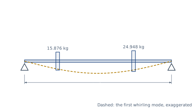
Drawn for the default inputs. It redraws as you change them.
Results are estimates. They do not replace the governing code, class or flag requirements, or a check by a competent person. Report a problem
Introduction
Every rotating shaft has speeds at which it whirls violently: its critical speeds. At the first critical speed, the speed of rotation matches the shaft's natural frequency of lateral vibration. A shaft carrying gears, pulleys or a fan must run well away from it. A 1 in steel shaft on bearings 31 in apart, carrying gears of 35 and 55 lbf, reaches its first critical speed at about 1 325 rpm.
This calculator gives the first critical speed of a uniform shaft on two bearings with up to three masses. It uses Rayleigh's method with the static deflections under the weights, adds the shaft's own mass by Dunkerley's rule, and shows the pure Dunkerley estimate and the shaft-alone value for comparison. It is for designers of fans, pumps, conveyors and machine spindles, and follows Shigley chapter 7.
Formulas
Static deflection by superposition, with the influence coefficient of a simply supported span (load at a, b = L − a):
δ(x, a) = b x (L² − b² − x²) / (6 E I L)          for x ≤ a
δ(x, a) = a (L − x)(2 L x − x² − a²) / (6 E I L)   for x > a
y_j = Σ W_i δ(x_j, a_i)
Rayleigh's method (Shigley eq. 7-23) and the uniform shaft (eq. 7-22):
ω_R = √( g Σ W_i y_i / Σ W_i y_i² )
ω_s = (π / L)² √( E I / (ρ A) )
W_i = m_i g — weight of mass i at distance a_i from the left bearing; L — bearing span
E — Young's modulus; I = π (d⁴ − d_i⁴)/64; A — section area; ρ — shaft density
n = 60 ω / (2π) in rpm
Assumptions and limitations
The shaft is uniform, solid or hollow, on two simple supports at its ends. Stepped shafts, overhung discs and fixed bearings need a full deflection analysis.
The masses are points. Their gyroscopic effect and rotary inertia are neglected.
Rayleigh's method slightly overestimates the critical speed and Dunkerley's rule underestimates it. The true value lies between the two.
Flexible bearings, housings and foundations lower the critical speed. Measure or model them for high-speed machines.
Worked example
A 1 in steel shaft (E = 30 000 ksi, 0.282 lbf/in³) runs in bearings 31 in apart. It carries a 35 lbf gear 7 in from the left bearing and a 55 lbf gear 23 in from it. These are the data of Shigley Example 7-5.
I = π × 1⁴ / 64 = 0.0491 in⁴. Influence coefficients: a11 = 2.061, a12 = 1.734 and a22 = 2.472, all × 10⁻⁴ in/lbf.
Rayleigh: Σ W y = 1.668 and Σ W y² = 0.03109, so ω = √(386.1 × 1.668 / 0.03109) = 143.9 rad/s, or 1 374 rpm.
Dunkerley with the gears only: 1 301 rpm, the lower bound.
Shaft alone: (π/31)² × √(E I / (ρ A)) = 520.4 rad/s, or 4 969 rpm.
Combined: 1/ω² = 1/143.9² + 1/520.4², so ω = 138.7 rad/s, or 1 325 rpm.
The shaft should run well below about 1 300 rpm, or be made stiffer if it must run faster.
The worked example, drawn by the same code as the live drawing above.
FAQ
What is the critical speed of a shaft?
The speed at which the shaft's rotation excites its natural frequency of bending vibration. The shaft then whirls with large deflections.
How far from the critical speed should a shaft run?
Keep a clear margin either side. Many designers aim for a first critical speed well above the highest operating speed, so the machine never passes through it.
What is the difference between Rayleigh and Dunkerley?
Rayleigh's method uses the deflected shape and gives a slightly high answer. Dunkerley's rule adds the effect of each mass separately and gives a low one.
How do I raise the critical speed?
Increase the diameter, shorten the bearing span, or move heavy masses towards the bearings. A hollow shaft of the same outside diameter is lighter and runs faster.
Can a shaft run above its critical speed?
Yes, many turbines and centrifuges do, but they must pass through it quickly and with good balance and damping.
Does the shaft's own weight matter?
Yes. In the example, it lowers the critical speed from 1 374 to 1 325 rpm.
Before every release the calculator must reproduce each case below. The note under each case says where the expected answer comes from: a standard, a textbook, a published table, or a hand calculation shown in full.
Shigley Example 7-5 influence coefficients (1 in shaft, 31 in span, 30 Mpsi): a11 = 2.061, a12 = 1.734, a22 = 2.472 × 10⁻⁴ in/lbfShigley's Mechanical Engineering Design, 10th ed., Example 7-5 (Table A-9 deflection formulas)
Example 7-5: Rayleigh 143.9 rad/s (1 374 rpm), Dunkerley 136.2 rad/s (1 301 rpm), shaft alone 520.4 rad/s (4 969 rpm), combined 1 325 rpmShigley 10th ed., Example 7-5 data with eqs. 7-22, 7-23 and 7-32 (hand calculation)
Single central mass: Rayleigh and Dunkerley both give the exact ω = √(48 E I / (m L³))Simply supported beam, central load: δ = W L³ / (48 E I) (Roark Table 8.1)
Uniform shaft alone: ω_s = (π/L)² √(EI/(ρA)); a hollow shaft of the same outside diameter runs fasterShigley 10th ed., eq. 7-22
Operating speed near critical warns (1 300 rpm against 1 325 rpm); ratio is reportedBehaviour check: warnings and rejected inputs
A mass outside the span, a bore larger than the shaft and no mass at all are rejectedBehaviour check: warnings and rejected inputs
Worked example of the article: the calculator reproduces 1 374 rpm, 1 301 rpm, 4 969 rpm, 1 325 rpm to the digits printedThe worked example on this page, to the digits printed
Assumptions and sources
Assumptions and limits
A uniform round shaft, solid or hollow, on two simple supports (short or self-aligning bearings) at its ends; the masses are rigid discs treated as points, and their gyroscopic effect and rotary inertia are neglected.
Rayleigh's method uses the static deflection curve under the weights as the mode shape (Shigley eq. 7-23); it slightly overestimates the true first critical speed. Dunkerley's rule underestimates it, so the two bracket the answer.
The shaft's own mass enters through its uniform-shaft critical speed (Shigley eq. 7-22) combined with the masses by Dunkerley's rule, 1/ω² = 1/ω_R² + 1/ω_s², the modification Shigley suggests in Example 7-5; the result is conservative.
Stepped shafts, overhung masses, flexible bearings and supports, and fixed ends change the critical speed and are not covered. Bearing and housing flexibility lowers it.
Sources
Budynas and Nisbett, Shigley's Mechanical Engineering Design, 10th ed., §7-6 Critical speeds for shafts: eqs. 7-22 (uniform shaft), 7-23 (Rayleigh), 7-32 (Dunkerley), Table A-9 (beam deflections) and Example 7-5
Roark's Formulas for Stress and Strain, 8th ed., Table 8.1 case 1e (simply supported beam with a point load, deflection equations)
Cite this calculator
Papandreou, C. (2026). Shaft critical speed calculator (Rayleigh and Dunkerley). Engineering Bible. https://engineeringbible.com/mechanical/shaft-critical-speed/
Embed this calculator on your site
Copy this HTML into your page. The calculator stays free to use and links back here.