Cutoff frequency of RC, RL, LC and RLC low-pass and high-pass filters, with Q, attenuation in dB and phase at a frequency, or the component for a target cutoff.
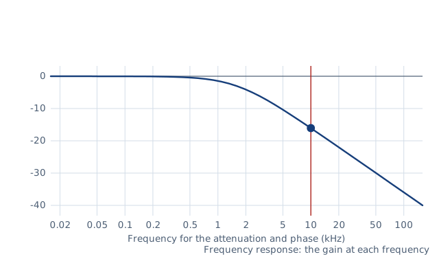
Drawn for the default inputs. It redraws as you change them.
Results are estimates. They do not replace the governing code, class or flag requirements, or a check by a competent person. Report a problem
Introduction
The cutoff frequency of a filter is where its output falls to 0.707 of the input, which is −3 dB or half the power. For a first-order RC filter it is f_c = 1 / (2π R C). A 1 kΩ resistor with a 100 nF capacitor gives 1.59 kHz. Beyond the cutoff, a first-order filter loses 20 dB per decade, and a second-order LC filter 40 dB.
This calculator gives the cutoff frequency of RC and RL filters, and the natural frequency, Q and −3 dB frequency of series RLC and loaded LC filters, both low-pass and high-pass. It also gives the gain in dB and the phase at any frequency, and finds the capacitor or inductor for a target frequency. It is for students, hobbyists and engineers designing audio, sensor, power-supply and radio filters.
Formulas
First-order RC and RL filters, with x = f / f_c:
f_c = 1 / (2π R C)   or   f_c = R / (2π L)
low-pass:   |H| = 1 / √(1 + x²),   φ = −arctan x
high-pass:  |H| = x / √(1 + x²),   φ = 90° − arctan x
Second-order filters, with x = f / f0:
f0 = 1 / (2π √(L C))
Q = √(L / C) / R  (series RLC),   Q = R √(C / L)  (LC with load R)
low-pass:   H = 1 / (1 − x² + j x / Q)
high-pass:  H = −x² / (1 − x² + j x / Q)
R — resistance, Ω; C — capacitance, F; L — inductance, H (entered in µH)
|H| — output over input voltage; gain in dB = 20 log10 |H|; φ — phase
Q — quality factor; 0.707 gives the flattest passband
Assumptions and limitations
The components are ideal. A real coil has resistance, which can be added to R in the series RLC circuit.
The source has zero impedance and the output feeds an open circuit. A load across the output of an RC or RL filter lowers the effective resistance and moves the cutoff.
In the loaded LC filter, the load resistor sits across the output component. Its value sets the Q, so the filter must be designed for the load it drives.
A second-order filter has its −3 dB point at f0 only when Q = 0.707. Above that it peaks near f0, below that it rolls off early.
For a target frequency, the second-order component is chosen so that f0 equals the target.
Worked example
An RC low-pass filter has R = 1 kΩ and C = 100 nF. What is its cutoff frequency, and how much does it attenuate a 10 kHz signal?
Before every release the calculator must reproduce each case below. The note under each case says where the expected answer comes from: a standard, a textbook, a published table, or a hand calculation shown in full.
RC low-pass 1 kΩ, 100 nF: f_c = 1.592 kHz; at 10 kHz |H| = 0.1572 (−16.07 dB), phase −80.96°Horowitz and Hill §1.7, f_3dB = 1/(2πRC) and |H| = 1/√(1 + (f/f_c)²); hand calculation
At the cutoff a first-order filter is −3.01 dB with ±45° of phase; RL high-pass f_c = R/(2πL) and the L for 1 kHz with 100 Ω is 15.92 mHDefinition of the half-power point; Boylestad ch. 21, R-L filters
Second order: Q = 0.707 puts the −3 dB point at f0 (Butterworth); Q = 0.5 (critical damping) at 0.6436 f0 low-pass and 1.554 f0 high-passStandard second-order results: √(√2 − 1) = 0.6436 for two equal real poles
Series RLC with Q = 1: resonant peak 1.25 dB; at f0 the low-pass gain is Q (0 dB) with −90° phaseSecond-order peaking Q/√(1 − 1/(4Q²)); |H(f0)| = Q
Component for a target: RC with 10 kΩ for 1 kHz needs 15.92 nF; LC with 10 mH for f0 = 1 kHz needs 2.533 µFC = 1/(2π f R); C = 1/((2π f)² L)
Invalid entries are rejected: an inductor for an RC filter, zero resistance, zero frequencyBehaviour check: warnings and rejected inputs
Worked example of the article: the calculator reproduces 1.59 kHz, −16.1, 0.157 to the digits printedThe worked example on this page, to the digits printed
Assumptions and sources
Assumptions and limits
Components are ideal: the inductor has no resistance and the capacitor no leakage or ESR, apart from the resistor R of the circuit; a coil's own resistance can be added to R in the series RLC circuit.
The source has zero impedance and, for the RC, RL and series RLC circuits, the output drives an open circuit; a load in parallel with the output changes the cutoff and, for second-order filters, the Q.
In the LC circuit with a load resistor, the inductor (low-pass) or capacitor (high-pass) is in series and the load R sits across the other component, which is the output.
For second-order filters the −3 dB frequency equals the natural frequency f0 only at Q = 0.707 (Butterworth); the component for a target is chosen so that f0 equals the target, and the resulting −3 dB frequency is shown.
The cutoff is the −3 dB (half-power) point, where the output voltage is 0.707 of the input and the phase shift is 45° for a first-order filter.
Sources
Horowitz and Hill, The Art of Electronics, 3rd ed., §1.7 (RC filters, f_3dB = 1/(2πRC)) and §6.2 (LC filters and Q)
Boylestad, Introductory Circuit Analysis, 13th ed., ch. 21 (decibels, filters and Bode plots: R-C and R-L low-pass and high-pass filters)
Hughes, Electrical and Electronic Technology, 12th ed., the chapters on frequency response and resonance (second-order response, Q and damping)
Cite this calculator
Papandreou, C. (2026). Filter cutoff frequency calculator (RC, RL, LC). Engineering Bible. https://engineeringbible.com/electrical/filter-cutoff/
Embed this calculator on your site
Copy this HTML into your page. The calculator stays free to use and links back here.