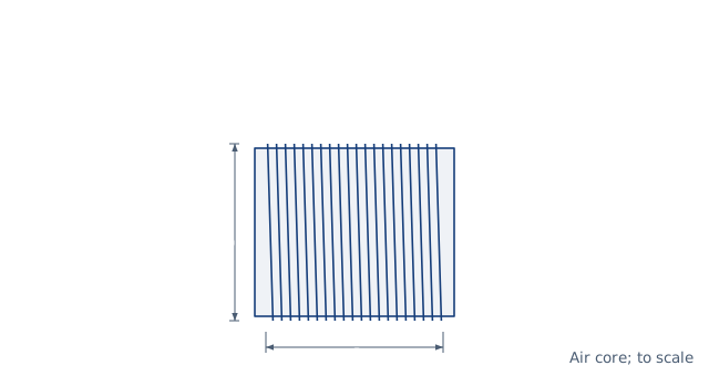
Drawn for the default inputs. It redraws as you change them.
Results are estimates. They do not replace the governing code, class or flag requirements, or a check by a competent person. Report a problem
Introduction
The inductance of an air-core coil depends on the number of turns squared and on the coil's shape. Wheeler's formula, published in 1928, gives it for a single-layer coil in microhenries from its diameter and length in inches: L = d² N² / (18 d + 40 l). Twenty turns on a former 1 in across, wound over 1 in, give 6.90 µH.
This calculator gives the inductance of a single-layer or multilayer air-core coil by Wheeler's formulas, or of a long solenoid by the physics formula μ0 N² A / l. It also works backwards to the turns for a target inductance. For single-layer coils it shows the exact current-sheet value with Nagaoka's coefficient for comparison. It is for radio amateurs, students and engineers winding coils for tuned circuits, filters and crossovers.
Formulas
Wheeler's formulas, with dimensions in inches and L in µH:
single layer:  L = d² N² / (18 d + 40 l)
multilayer:    L = 0.8 a² N² / (6 a + 9 b + 10 c)
Long solenoid and current sheet, in SI units:
L = μ0 N² A / l,   A = π d² / 4
L_sheet = K × μ0 N² A / l
Turns for a target inductance, single layer:
N = √(L × (18 d + 40 l)) / d
N — number of turns; d — coil diameter to the wire centres
l, b — winding length; a — mean radius of a multilayer coil
c — radial depth of the winding (outer minus inner radius)
μ0 = 4π × 10⁻⁷ H/m; K — Nagaoka's coefficient, from the ratio d / l
Assumptions and limitations
The coil has an air core, or a former of plastic, ceramic or wood. A ferrite or iron core raises the inductance many times.
Wheeler's single-layer formula is within about 1 % when the coil is longer than 0.4 times its diameter. Shorter coils are better estimated by the current-sheet value.
The multilayer formula is within about 1 % when 6a, 9b and 10c are roughly equal. The calculator warns when they differ widely.
The long-solenoid formula ignores the weaker field at the ends. It overestimates any coil that is not much longer than it is wide.
Close to the coil's self-resonant frequency, its self-capacitance makes the effective inductance rise.
Worked example
A coil has 20 turns on a former 1 in in diameter, wound over a length of 1 in. What is its inductance?
Nagaoka's coefficient for d / l = 1 is 0.6884, so the current sheet gives 0.6884 × 10.03 = 6.90 µH.
Wheeler's simple formula agrees with the exact current-sheet value to 0.1 %. The long-solenoid formula is 45 % too high for a coil this short. To reach 10 µH on the same former takes √(10 × 58) = 24.1 turns.
The worked example, drawn by the same code as the live drawing above.
FAQ
How do I calculate the inductance of an air-core coil?
For a single layer, use Wheeler's formula L = d² N² / (18 d + 40 l) with inches and microhenries. It is within about 1 % for most practical coils.
How many turns do I need for a given inductance?
Inductance rises with the square of the turns. Doubling the turns on the same length gives four times the inductance.
Why is the long-solenoid formula wrong for my coil?
It assumes the field is uniform along the whole coil. In a short coil the field spreads out at the ends, so the true value is lower by Nagaoka's coefficient.
What diameter should I measure?
The diameter to the centre of the wire, which is the former diameter plus one wire diameter.
Does the wire gauge change the inductance?
Only slightly, through the winding length and the diameter to the wire centres. It mainly sets the resistance and the current rating.
What is Nagaoka's coefficient?
A factor between 0 and 1 that corrects the long-solenoid formula for a coil of finite length. It is 0.6884 for a coil as long as it is wide.
Before every release the calculator must reproduce each case below. The note under each case says where the expected answer comes from: a standard, a textbook, a published table, or a hand calculation shown in full.
Single layer, 1 in by 1 in, 20 turns: Wheeler 400/58 = 6.897 µH; current sheet 0.6884 × 10.03 = 6.903 µH (within 0.1 %)Wheeler, Proc. IRE 16 (1928) single-layer formula; Nagaoka (1909) coefficient for d/l = 1
Nagaoka coefficients match the published tables: d/l = 0.5 → 0.8181, 1 → 0.6884, 2 → 0.5255, and → 1 for a very long coilNagaoka (1909) and Grover, Inductance Calculations, tables of K
Turns for 10 µH on the 1 in by 1 in former: N = √(10 × 58) = 24.08, and that N gives 10 µH backWheeler single-layer formula solved for N
Multilayer, mean radius 0.5 in, length 0.5 in, depth 0.45 in, 100 turns: 0.8 × 0.25 × 10⁴ / (3 + 4.5 + 4.5) = 166.7 µHWheeler, Proc. IRE 16 (1928) multilayer formula, hand calculation
Long solenoid, 1 000 turns, 10 mm diameter, 0.5 m long: μ0 N² A / l = 197.4 µH, within 1 % of the current sheetPhysics long-solenoid formula L = μ0 N² A / l; Nagaoka K → 1 for l ≫ d
Invalid entries are rejected: zero diameter, zero turns, a winding deeper than the mean diameterBehaviour check: warnings and rejected inputs
Worked example of the article: the calculator reproduces 6.90, 10.03, 6.90, 0.6884 to the digits printedThe worked example on this page, to the digits printed
Assumptions and sources
Assumptions and limits
The coil has no core, or a core of a non-magnetic material such as plastic, wood or ceramic; a ferrite or iron core multiplies the inductance by its effective permeability.
Wheeler's single-layer formula uses the diameter to the centre of the wire and the winding length; Wheeler gives it as accurate to about 1 % when the length is more than 0.4 times the diameter.
Wheeler's multilayer formula uses the mean radius, the winding length and the radial depth of the winding; it is accurate to about 1 % when 6a, 9b and 10c are about equal, and less otherwise.
The long-solenoid formula μ0 N² A / l ignores the field at the ends, so it overestimates a short coil; the current-sheet value with Nagaoka's coefficient is exact for a thin, evenly wound single layer and is shown for comparison.
Self-capacitance, the wire's own inductance and the change of current distribution with frequency are ignored; they matter near the coil's self-resonant frequency.
Sources
Wheeler, H. A., Simple Inductance Formulas for Radio Coils, Proceedings of the IRE, vol. 16, no. 10, 1928, pp. 1398–1400 (single-layer and multilayer formulas)
Nagaoka, H., The Inductance Coefficients of Solenoids, Journal of the College of Science, Imperial University of Tokyo, vol. 27, art. 6, 1909 (coefficient K for d/l = 1: 0.6884)
Grover, F. W., Inductance Calculations, Van Nostrand 1946 (Dover reprint), the chapter on single-layer coils and its tables of Nagaoka's coefficient
Cite this calculator
Papandreou, C. (2026). Air-core coil inductance calculator. Engineering Bible. https://engineeringbible.com/electrical/coil-inductance/
Embed this calculator on your site
Copy this HTML into your page. The calculator stays free to use and links back here.