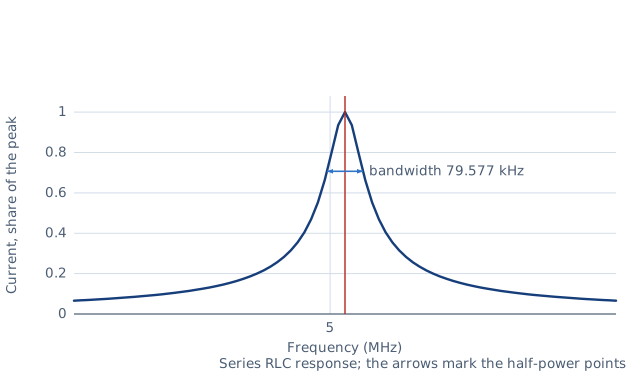
Drawn for the default inputs. It redraws as you change them.
Results are estimates. They do not replace the governing code, class or flag requirements, or a check by a competent person. Report a problem
Introduction
An inductor and a capacitor together resonate at the frequency where their reactances are equal and cancel. That frequency is f0 = 1 / (2π √(L C)). A 10 µH coil with a 100 pF capacitor resonates at 5.03 MHz, and a 253 µH coil with the same capacitor at 1 MHz.
This calculator gives the resonant frequency from L and C, or the L or C needed for a target frequency. It also gives the characteristic impedance, and from the series resistance of the coil the quality factor Q, the bandwidth, the two −3 dB frequencies and the dynamic resistance of a parallel tank. It is for radio amateurs, students and engineers designing tuned circuits, oscillators, filters and matching networks.
Formulas
Resonant frequency and the component for a target frequency:
Characteristic impedance, quality factor and bandwidth with a series resistance R:
Z0 = √(L / C) = 2π f0 L = 1 / (2π f0 C)
Q = Z0 / R
BW = f0 / Q = R / (2π L)
f1, f2 = f0 × (√(1 + 1/(4Q²)) ∓ 1/(2Q))
Dynamic resistance of a parallel tank at resonance:
R_D = L / (C R) = Q² R
L — inductance, H (entered in µH); C — capacitance, F
R — total series loss resistance of the coil and capacitor, Ω
f1, f2 — the half-power (−3 dB) frequencies
Assumptions and limitations
One resistance in series with L and C stands for all the losses. A coil's resistance rises with frequency through the skin effect, so use its value at f0.
The series and parallel Q formulas agree when Q is high. Below about 10 the parallel tank's resonance shifts slightly below f0.
Stray capacitance of the coil, the wiring and the board adds to C. At several megahertz a few picofarads lower the frequency noticeably.
The capacitor's value changes with temperature and, for some ceramics, with voltage. C0G ceramic and mica capacitors stay stable.
Worked example
A 10 µH coil with a series resistance of 5 Ω is tuned by a 100 pF capacitor. Find the resonant frequency, Q and bandwidth.
L C = 10 × 10⁻⁶ × 100 × 10⁻¹² = 10⁻¹⁵ s², so √(L C) = 3.162 × 10⁻⁸ s.
f0 = 1 / (2π × 3.162 × 10⁻⁸) = 5.03 MHz.
Characteristic impedance: √(10⁻⁵ / 10⁻¹⁰) = 316 Ω, the reactance of each part at f0.
Q = 316 / 5 = 63.2.
Bandwidth: 5.03 MHz / 63.2 = 79.6 kHz.
As a parallel tank: R_D = 10⁻⁵ / (10⁻¹⁰ × 5) = 20 kΩ.
So the circuit passes about 4.99 to 5.07 MHz within 3 dB of its peak.
The worked example, drawn by the same code as the live drawing above.
FAQ
How do I calculate the resonant frequency of an LC circuit?
Use f0 = 1 / (2π √(L C)) with henries and farads. For 10 µH and 100 pF that is 5.03 MHz.
What capacitor do I need for a given frequency?
C = 1 / ((2π f)² L). With a 253 µH coil, 1 MHz needs 100 pF.
What is the Q of an LC circuit?
The ratio of the reactance at resonance to the loss resistance. A higher Q gives a sharper peak and a narrower bandwidth.
How is bandwidth related to Q?
The −3 dB bandwidth is the resonant frequency divided by Q. A 5 MHz circuit with Q = 50 has a bandwidth of 100 kHz.
What is the difference between series and parallel resonance?
A series LC circuit has its lowest impedance at resonance. A parallel tank has its highest, equal to the dynamic resistance L / (C R).
Why is my measured frequency lower than calculated?
Stray capacitance adds to C, and the coil's self-capacitance does the same. Both lower the frequency.
Before every release the calculator must reproduce each case below. The note under each case says where the expected answer comes from: a standard, a textbook, a published table, or a hand calculation shown in full.
Medium-wave tuning: 1 MHz with 100 pF needs 253.3 µH, and 253.3 µH needs 100 pF backL = 1/((2πf)² C), C = 1/((2πf)² L); the textbook 1 MHz / 100 pF / 253 µH broadcast-band case
The −3 dB frequencies are geometric about f0 (f1 f2 = f0²) and differ by exactly the bandwidthSeries RLC half-power frequencies f1,2 = f0(√(1 + 1/(4Q²)) ∓ 1/(2Q))
Limiting case: zero resistance gives no Q, bandwidth or dynamic resistance, and a warningQ = Z0/R → ∞ as R → 0
Invalid entries are rejected: zero inductance, zero capacitance, negative resistanceBehaviour check: warnings and rejected inputs
Worked example of the article: the calculator reproduces 5.03 MHz, 316 Ω, 63.2, 79.6 kHz, 20 kΩ to the digits printedThe worked example on this page, to the digits printed
Assumptions and sources
Assumptions and limits
The inductor and capacitor are ideal apart from one resistance R in series with them, which stands for the coil's winding and skin-effect resistance and any capacitor ESR at the resonant frequency.
Q, bandwidth and the −3 dB frequencies are those of the series RLC circuit; for high Q they also describe a parallel tank whose coil has the series resistance R.
A parallel tank with a lossy coil resonates, in the sense of a purely resistive impedance, at f0 √(1 − 1/Q²); the difference from f0 is 0.5 % at Q = 10 and smaller above.
Stray capacitance of the coil and the wiring adds to C and lowers the frequency; at high frequencies it can be several picofarads.
Sources
Hughes, Electrical and Electronic Technology, 12th ed., the chapters on series and parallel resonance (Q factor, bandwidth f0 / Q)