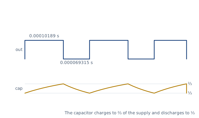
Drawn for the default inputs. It redraws as you change them.
Results are estimates. They do not replace the governing code, class or flag requirements, or a check by a competent person. Report a problem
Introduction
The 555 timer sets its timing with resistors and a capacitor. In the astable circuit it oscillates at f = 1.44 / ((R1 + 2 R2) C). With R1 = 4.7 kΩ, R2 = 10 kΩ and C = 10 nF, it runs at about 5.84 kHz with the output high 59.5 % of the time. In the monostable circuit one trigger gives one pulse of 1.1 R1 C.
This calculator gives the frequency, period, high and low times and duty cycle of an astable 555, or the pulse width of a monostable one. A design mode works backwards from a target frequency and duty cycle to R1 and R2, then picks the nearest E24 resistors. Type values as they are marked on parts, such as 4k7 or 10n. It is for hobbyists, students and engineers building oscillators, flashers, tone generators and delays.
Formulas
Astable, with R1 from the supply to the discharge pin and R2 from the discharge pin to the threshold and trigger pins:
t_H = ln 2 × (R1 + R2) × C ≈ 0.693 (R1 + R2) C
t_L = ln 2 × R2 × C ≈ 0.693 R2 C
f = 1 / (t_H + t_L) ≈ 1.44 / ((R1 + 2 R2) C)
D = t_H / (t_H + t_L) = (R1 + R2) / (R1 + 2 R2)
Monostable, with R1 from the supply to the discharge and threshold pins:
t = ln 3 × R1 × C ≈ 1.1 R1 C
Design from a target frequency f and duty cycle D:
S = R1 + 2 R2 = 1 / (ln 2 × f × C)
R1 = (2D − 1) × S,   R2 = (1 − D) × S
t_H, t_L — time the output is high and low, s
f — frequency, Hz; D — duty cycle, the share of each period the output is high
R1, R2 — timing resistors, Ω; C — timing capacitor, F
Assumptions and limitations
The capacitor swings between one third and two thirds of the supply. Both thresholds scale with the supply, so the timing does not depend on the supply voltage.
The calculator uses ln 2 and ln 3 exactly. The datasheet rounds them to 0.693, 1.44 and 1.1, which shifts the results by less than 0.2 %.
Real circuits differ by the component tolerances. A 10 % capacitor moves the frequency by up to 10 %.
Electrolytic capacitors leak, which lengthens long delays. Use film or ceramic capacitors where accuracy matters.
The basic astable circuit always gives a duty cycle above 50 %, because the capacitor charges through both resistors but discharges through R2 only.
Worked example
An astable 555 has R1 = 4k7, R2 = 10k and C = 10n. What frequency and duty cycle does it give?
Before every release the calculator must reproduce each case below. The note under each case says where the expected answer comes from: a standard, a textbook, a published table, or a hand calculation shown in full.
Monostable 100 kΩ and 10 µF: t = 1.1 R C = 1.10 s (ln 3 R C = 1.0986 s)TI NE555 datasheet SLFS022, monostable t_w = 1.1 R_A C
Design 1 kHz, 60 % with 100 nF: exact R1 2.885 kΩ, R2 5.771 kΩ; E24 3 kΩ and 5.6 kΩ give 1.016 kHz and 60.6 %Inverting f = 1/(ln2 (R1 + 2R2) C) and D = (R1 + R2)/(R1 + 2R2); IEC 60063 E24 values
Limiting case: R1 much smaller than R2 gives a duty cycle just above 50 %; marking notation and plain microfarads read correctlyD = (R1 + R2)/(R1 + 2R2) → 1/2 as R1 → 0; IEC 60062 letter-digit code
Invalid entries are rejected: text, two values, zero, and a duty cycle of 50 %Behaviour check: warnings and rejected inputs
Worked example of the article: the calculator reproduces 5.84 kHz, 59.5 % to the digits printedThe worked example on this page, to the digits printed
Assumptions and sources
Assumptions and limits
The timing follows the ideal 555 thresholds: the capacitor charges and discharges between 1/3 and 2/3 of the supply in astable mode, and charges from 0 to 2/3 in monostable mode, so the results do not depend on the supply voltage.
The exact factors ln 2 = 0.6931 and ln 3 = 1.0986 are used; the datasheet rounds them to 0.693, 1.44 and 1.1, which changes the results by less than 0.2 %.
Component tolerances, capacitor leakage, the internal propagation delays and the discharge transistor's saturation voltage are ignored; they matter at very high frequencies and with large electrolytic capacitors.
In the basic astable circuit the capacitor charges through R1 and R2 but discharges through R2 only, so the duty cycle is always above 50 %; a diode across R2 or a different circuit is needed for 50 % or less.
Resistors are typed in ohms or with a prefix (470, 4k7, 1M); capacitors are typed with a prefix (100p, 10n, 4u7), and a plain number is microfarads.