Hydro power from flow and head: penstock friction by Darcy or Hazen–Williams, net head, electrical power, yearly energy and turbine types for the head.
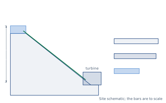
Drawn for the default inputs. It redraws as you change them.
Results are estimates. They do not replace the governing code, class or flag requirements, or a check by a competent person. Report a problem
Introduction
How much power can a stream make? Hydro power is water density × gravity × flow × head × efficiency. A stream that sends 50 L/s down a 40 m drop carries 19.6 kW. After the losses in the pipe and a turbine and generator that are 60 % efficient together, it gives about 11 kW of electricity, around the clock.
This calculator works out the friction loss in the penstock, the net head, the hydraulic and electrical power and the yearly energy. It lists the turbine types whose head range covers your net head. It is for landowners, small hydro developers and students making a first assessment of a site.
Formulas
Power and net head:
P = ρ g Q H_n η
H_n = H_g − h_f − K v² / (2g)
Friction loss in the penstock:
Darcy–Weisbach:  h_f = f (L / D) v² / (2g),  f from Colebrook
Hazen–Williams:  h_f = 10.67 L Q^1.852 / (C^1.852 D^4.8704)
ρ — water density, 1 000 kg/m³; g = 9.81 m/s²; Q — design flow
H_g — gross head; H_n — net head at the turbine
η — overall efficiency from water to wire
L, D — penstock length and inside diameter; v — water velocity; f — Darcy friction factor
K — sum of the fitting loss coefficients; C — Hazen–Williams coefficient
Turbine types by net head, from ESHA Table 6.3:
Turbine
Net head range
Kaplan and propeller
2 to 40 m
Crossflow
5 to 200 m
Francis
25 to 350 m
Turgo
50 to 250 m
Pelton
50 to 1 300 m
Assumptions and limitations
The gross head is the vertical drop from the intake water level to the turbine. Measure it with a level survey or GPS, not a map.
The overall efficiency covers the turbine, the drive and the generator. ESHA gives best turbine efficiencies of 85 % for Turgo to 94 % for Francis. The generator, the drive and running at part flow lower the overall figure, and the page defaults to 60 %.
The yearly energy assumes the design flow for the share of the year you enter. A real stream varies with the season, and some water must stay in the stream.
The turbine list uses head only. Flow, speed and cost narrow the choice, and manufacturers' charts use head and flow together.
Worked example
A stream supplies 50 L/s to a 200 m penstock of 200 mm plastic pipe, with a roughness of 0.0015 mm. The gross head is 40 m and the water is at 10 °C, 1.307 mm²/s. The turbine and generator are 60 % efficient and run 80 % of the year. What does the plant deliver?
Velocity: 0.05 / (π × 0.2² / 4) = 1.59 m/s.
Reynolds number: 1.59 × 0.2 / 1.307 × 10⁻⁶ = 243 500, so f = 0.0151 from Colebrook.
Energy per year: 11.19 × 8 760 × 0.80 = 78 400 kWh.
At 38 m net head, ESHA lists Kaplan, crossflow and Francis turbines. The flow, the speed and the cost then decide between them.
The worked example, drawn by the same code as the live drawing above.
FAQ
How do you calculate hydro power?
Multiply 9.81 by the flow in m³/s, the net head in metres and the efficiency to get kW. 50 L/s at 38 m and 60 % gives 11.2 kW.
What is the difference between gross head and net head?
Gross head is the vertical drop. Net head is what remains at the turbine after the friction and fitting losses in the pipe.
How big should the penstock be?
Large enough to keep the friction loss a small share of the gross head, which the page shows. Beyond a loss of one third of the gross head, more flow gives less power.
Which turbine should I use?
Pelton and Turgo turbines suit high heads, Francis and crossflow medium heads, and Kaplan or propeller turbines low heads. The table above gives ESHA's ranges.
How much power do I get from 1 L/s?
About 0.0098 kW per metre of net head before efficiency. At 60 % overall, 1 L/s over 100 m gives about 0.59 kW.
Is Hazen–Williams or Darcy–Weisbach better?
Darcy–Weisbach works for any fluid, pipe and temperature. Hazen–Williams is a simpler formula for water at ordinary temperatures, and the two agree closely for this example.
Before every release the calculator must reproduce each case below. The note under each case says where the expected answer comes from: a standard, a textbook, a published table, or a hand calculation shown in full.
1 m³/s over a 10 m net head is 98.07 kW of hydraulic power; at 80 % it delivers 78.45 kWESHA 2004, eq. 6.1: P = ρ Q g H η with ρ = 1 000 kg/m³, g = 9.80665 m/s²
50 L/s, 200 m of 200 mm plastic pipe: v 1.592 m/s, Re 243 500, f 0.0151, loss 1.95 m, net 38.05 m, 11.19 kW at 60 %Hand calculation: Darcy–Weisbach with the Colebrook friction factor (Haaland gives 0.0150, within 1 %)
Hazen–Williams with C = 150 gives 1.97 m for the same pipe, within 1 % of Darcy–Weisbach; 100 L/s in 300 mm, 1 km, C 130 loses 6.42 mHazen–Williams SI form h_f = 10.67 L Q^1.852 / (C^1.852 D^4.8704), hand calculation
ESHA Table 6.3: 3 m Kaplan only; 38 m Kaplan, crossflow, Francis; 100 m crossflow, Francis, Turgo, Pelton; 500 m Pelton onlyESHA, Guide on How to Develop a Small Hydropower Plant (2004), Table 6.3 Range of heads
Fitting losses add K v²/2g: K = 2 at 1.59 m/s adds 0.258 m; a loss above a third of the gross head warnsMinor loss definition; maximum of Q (H_g − c Q²) at h_f = H_g/3
Losses that use up the gross head, a zero flow and an efficiency above 95 % are rejectedBehaviour check: warnings and rejected inputs
Worked example of the article: the calculator reproduces 1.59 m/s, 1.95 m, 38.05 m, 18.66 kW, 11.19 kW, 78 400 kWh to the digits printedThe worked example on this page, to the digits printed
Assumptions and sources
Assumptions and limits
Power is ρ g Q H_n η, where H_n is the net head: the gross head between intake and turbine minus the friction and fitting losses in the penstock at the design flow (ESHA 2004, eq. 6.1).
Friction by Darcy–Weisbach uses the Colebrook friction factor with the pipe roughness and the water viscosity (1.307 mm²/s at 10 °C by default); Hazen–Williams is an empirical formula for water at ordinary temperatures in pipes above about 50 mm; the third option takes the loss as a share of the gross head, for a first estimate.
The efficiency is from water to wire: turbine, drive and generator together. ESHA gives best turbine efficiencies of 0.85 (Turgo) to 0.94 (Francis); the generator, the drive and part-flow running lower the overall figure, so the default is 0.6.
Yearly energy assumes the design flow for the chosen share of the year; a real stream varies, so the energy should come from the flow duration curve less the residual flow left in the stream.
Turbine types are suggested from the net head ranges of ESHA Table 6.3 only; flow, speed, cavitation and cost narrow the choice, and manufacturers' selection charts use head and flow together.
Sources
ESHA (European Small Hydropower Association), Guide on How to Develop a Small Hydropower Plant, 2004: ch. 6, eq. 6.1 (P = ρ Q g H η), Table 6.3 (range of heads) and Table 6.7 (typical turbine efficiencies)
Colebrook, C. F., Turbulent flow in pipes, with particular reference to the transition region between the smooth and rough pipe laws, J. Inst. Civil Engineers 11 (1939) 133–156
Williams, G. S. and Hazen, A., Hydraulic Tables, 3rd ed., Wiley 1920 (Hazen–Williams formula; SI form h_f = 10.67 L Q^1.852 / (C^1.852 D^4.87))
Cite this calculator
Papandreou, C. (2026). Micro-hydro power calculator. Engineering Bible. https://engineeringbible.com/energy/micro-hydro/
Embed this calculator on your site
Copy this HTML into your page. The calculator stays free to use and links back here.