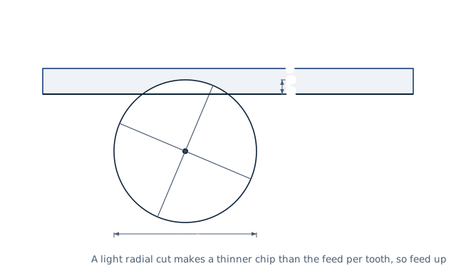
Drawn for the default inputs. It redraws as you change them.
Results are estimates. They do not replace the governing code, class or flag requirements, or a check by a competent person. Report a problem
Introduction
Chip load is the thickness of material each tooth of a milling cutter removes. It equals the feed rate divided by the number of teeth and the rpm. A four-flute end mill feeding at 40 in/min and turning at 5 000 rpm takes 0.002 in per tooth. Too small a chip rubs and wears the tool. Too large a chip breaks it.
This calculator gives the chip load from a feed rate, or the feed rate for a target chip load. It also corrects for radial chip thinning. When the cutter engages less than half its diameter, the real chip is thinner than the feed per tooth, so the feed can rise. The page is for CNC programmers and machinists using light-stepover, high-efficiency toolpaths.
v_f — feed rate; z — number of flutes; n — spindle speed in rpm
f_z — feed per tooth (chip load); h_ex — maximum chip thickness
a_e — radial depth of cut (stepover); D — cutter diameter
At a_e = D/2 or more, RCTF = 1 and the chip equals the feed per tooth
Assumptions and limitations
Every tooth cuts equally. Runout in the holder makes one tooth take a larger chip than the others.
The correction is for the side of a square-end mill. Ball-nose and chamfer cutters also thin the chip along the axis, which this page does not include.
Raising the feed restores the chip thickness. The machine, the holder and the tool must still take the higher feed rate, and the tool maker may set a limit.
The target chip load comes from the tool maker's table for the material and the cutter diameter.
Worked example
A 1/2 in four-flute end mill runs at 5 000 rpm with a 0.05 in stepover. The tool maker recommends a chip load of 0.002 in.
Before every release the calculator must reproduce each case below. The note under each case says where the expected answer comes from: a standard, a textbook, a published table, or a hand calculation shown in full.
Chip load: 40 in/min at 5 000 rpm with 4 flutes is 40 / (4 × 5 000) = 0.002 in per tooth; at half-diameter engagement the chip is not thinnedHarvey Tool: IPM = RPM × IPT × T (rearranged)
10 % engagement: RCTF = 1/√(1 − 0.8²) = 1.667; a 0.002 in chip needs 0.00333 in per tooth, 66.67 in/min instead of 40RCTF = 1/√(1 − (1 − 2 a_e/D)²) (hand calculation)
Metric round trip: 600 mm/min at 8 000 rpm, 3 flutes = 0.025 mm per tooth; with 1 mm of a 10 mm cutter the chip is 0.015 mm, and asking for 0.015 mm gives 600 mm/min backConsistency of the forward and inverse calculations
Very light cuts warn; a cut wider than the cutter, zero stepover and a fractional flute count are rejectedBehaviour check: warnings and rejected inputs
Worked example of the article: the calculator reproduces 1.667, 0.00333 in, 66.67 to the digits printedThe worked example on this page, to the digits printed
Assumptions and sources
Assumptions and limits
Chip load is the feed per tooth, f_z = feed rate / (teeth × rpm); every tooth is assumed to cut equally, with no runout.
At a radial engagement of half the diameter or more, the maximum chip thickness equals the feed per tooth. Below that the chip thins, and the maximum chip thickness is f_z × √(1 − (1 − 2 a_e/D)²).
The chip thinning factor applies to the side of a straight-flute or helical end mill with a square end; ball-nose and chamfer tools also thin the chip axially, which is not included.
Raising the feed by the thinning factor restores the chip thickness, not the cutting force per tooth; check the machine, the holder and the tool maker's maximum feed.