Skip to content
Engineering Bible

Results appear as you type. Use the arrow keys to move through them and Enter to open one.

Popular

↑ ↓ moveEnter openEsc close

Fatigue safety factor calculator (Goodman, Gerber, Soderberg)

Endurance limit of a steel part with the Marin factors and the fatigue safety factor by modified Goodman, Gerber, Soderberg and ASME-elliptic criteria.

Units
Chart of fatigue safety factor, modified goodman and fatigue safety factor, gerber and fatigue safety factor, soderberg against alternating nominal stress σ_a, computed by the calculator, with the current value 31.213 MPa marked: 3.02.10203040506070809002468Alternating nominal stress σ_a (MPa)Fatigue safety factor, modified Goodman: 3.02at alternating nominal stress σ_a 31.213 MPaFatigue safety factor, …Fatigue safety factor, …Fatigue safety factor, …Each point computed by the calculator; the red line marks your input
Drawn for the default inputs. It redraws as you change them.

Results are estimates. They do not replace the governing code, class or flag requirements, or a check by a competent person. Report a problem

Introduction

A part that sees a fluctuating stress can fail far below its tensile strength. For steel, a polished test bar in rotating bending survives indefinitely below its endurance limit, about half the tensile strength. A real part is rougher, larger and loaded differently, so the limit is cut by the Marin factors. A mean stress on top of the alternating stress cuts the allowable stress further, and the Goodman diagram measures by how much.

This calculator follows the stress-life method of Shigley's Mechanical Engineering Design. It estimates the endurance limit from the tensile strength, applies the factors for surface, size, loading, temperature and reliability, and gives the fatigue factor of safety by four criteria, plus the factor against yield on the first cycle. It is for mechanical engineers and students designing shafts, bolts, springs and brackets for infinite life.

Formulas

Endurance limit (Shigley eqs. 6-8 and 6-18):

S_e' = 0.5 S_ut  (S_ut ≤ 1 400 MPa),  700 MPa above
S_e = k_a k_b k_c k_d k_e k_f S_e'

Marin factors:

k_a = a S_ut^b: ground 1.58, −0.085; machined or cold-drawn 4.51, −0.265; hot-rolled 57.7, −0.718; as-forged 272, −0.995 (S_ut in MPa)
k_b = (d/7.62)^−0.107 (2.79 to 51 mm),  1.51 d^−0.157 (51 to 254 mm),  1 for axial load
k_c = 1 bending, 0.85 axial, 0.59 torsion
k_d = 0.975 + 0.432e-3 T − 0.115e-5 T² + 0.104e-8 T³ − 0.595e-12 T⁴  (T in °F)
k_e = 1, 0.897, 0.868, 0.814, 0.753 for 50, 90, 95, 99, 99.9 % reliability

Factors of safety for alternating stress σ_a and mean stress σ_m:

Goodman:       1/n = σ_a/S_e + σ_m/S_ut
Soderberg:     1/n = σ_a/S_e + σ_m/S_y
Gerber:        n = ½ (S_ut/σ_m)² (σ_a/S_e) [−1 + √(1 + (2 σ_m S_e / (S_ut σ_a))²)]
ASME-elliptic: n = 1 / √((σ_a/S_e)² + (σ_m/S_y)²)
Langer yield:  n_y = S_y / (σ_a + σ_m)
  • σ_a, σ_m — alternating and mean stresses, each multiplied by K_f
  • S_ut, S_y — ultimate and yield strength; d — diameter of a round section

Assumptions and limitations

  • The method is for steel and infinite life, a million cycles and more. Finite-life and other metals need an S-N curve.
  • The size factor holds for round sections in rotating bending or torsion. A non-rotating round uses an effective diameter of 0.370 d.
  • K_f multiplies both stresses, as for a ductile part that does not yield at the notch.
  • For torsion, enter shear stresses. The ultimate and yield strengths become 0.67 S_ut and 0.577 S_y.
  • Combined loads should be turned into von Mises alternating and mean stresses first and entered as bending.

Worked example

This is Shigley Example 6-10. A 1.5 in bar of cold-drawn AISI 1050 steel (S_ut = 100 ksi, S_y = 84 ksi) carries an axial load from 0 to 16 kip. A fillet gives K_f = 1.85.

  1. Surface: k_a = 4.51 × 689.5^−0.265 = 0.798. Axial loading: k_b = 1, k_c = 0.85.
  2. Endurance limit: S_e = 0.798 × 0.85 × 50 = 33.9 ksi.
  3. Stresses: area 1.767 in², so σ_a = σ_m = 1.85 × 8 / 1.767 = 8.375 ksi. Shigley rounds this to 8.38.
  4. Goodman: 1 / (8.375/33.9 + 8.375/100) = 3.02. Soderberg: 2.88.
  5. Gerber: 3.67, which Shigley prints as 3.66 from rounded values. ASME-elliptic: 3.75.
  6. First-cycle yield: 84 / (2 × 8.375) = 5.01.

All factors are well above 1, so the bar has infinite life and does not yield.
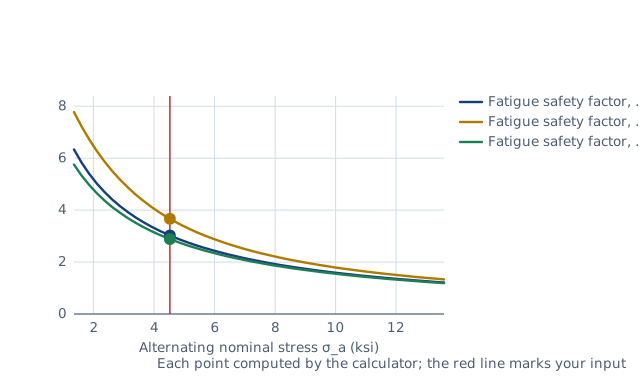
Chart of fatigue safety factor, modified goodman and fatigue safety factor, gerber and fatigue safety factor, soderberg against alternating nominal stress σ_a, computed by the calculator, with the current value 4.5271 ksi marked: 3.02.
The worked example, drawn by the same code as the live drawing above.

FAQ

What is the endurance limit of steel?

About half the tensile strength for a polished test bar, up to 700 MPa (100 ksi). A real part reaches only a fraction of that after the Marin factors.

Which criterion should I use, Goodman or Gerber?

Goodman is simple and slightly conservative, and common in design. Gerber follows test data more closely for ductile steels. Soderberg is the most conservative.

Why does a mean stress reduce fatigue strength?

A tensile mean stress holds cracks open, so they grow faster under the same alternating stress. A compressive mean stress helps.

What is the surface factor for a machined part?

k_a = 4.51 S_ut^−0.265 with S_ut in MPa. For a 520 MPa steel it is 0.860.

Do I apply the stress concentration factor to the mean stress?

For ductile materials Shigley applies K_f to both, as in Example 6-10. If the notch yields on the first cycle, the mean stress at the notch is lower.

What safety factor is enough?

It depends on how well the loads, the material and the stresses are known. The governing code or company practice sets the value.

Related calculators

What this calculator is checked against

Before every release the calculator must reproduce each case below. The note under each case says where the expected answer comes from: a standard, a textbook, a published table, or a hand calculation shown in full.

  1. Shigley Example 6-10: S_e = 33.9 kpsi, σa = σm = 8.38 kpsi, Gerber n_f = 3.66, ASME-elliptic 3.75, Langer n_y = 5.01Shigley's Mechanical Engineering Design, 10th ed., Example 6-10 (1.5 in AISI 1050 CD bar, 0 to 16 kip, K_f 1.85)
  2. Marin factors: Example 6-3 k_a = 4.51 × 520^−0.265 = 0.860; Example 6-4 k_b = (32/7.62)^−0.107 = 0.858; k_b at 100 mm = 1.51 × 100^−0.157 = 0.733Shigley 10th ed., Examples 6-3 and 6-4, Table 6-2, eq. 6-20
  3. Temperature factor eq. 6-27 against Table 6-4: 1.000 at 20 °C, 0.975 at 300 °C, 0.768 at 500 °C (within 0.005)Shigley 10th ed., Table 6-4 and eq. 6-27
  4. Criteria by hand: Goodman 1/(0.2470 + 0.0838) = 3.02, Soderberg 2.88; Gerber ≥ ASME-elliptic ≥ Goodman ≥ Soderberg ordering for this caseShigley 10th ed., Tables 6-6 to 6-8 (hand calculation)
  5. Limits: zero mean stress gives n = S_e/σ_a for every criterion; S_e' = 0.5 S_ut, capped at 700 MPa above 1 400 MPa; reliability 99 % gives k_e = 0.814Shigley 10th ed., eq. 6-8 and Table 6-5
  6. Rotating bending of a 32 mm machined shaft uses k_c = 1 and k_b = 0.858; Sy above Sut, a 300 mm shaft and 600 °C are rejectedBehaviour check: warnings and rejected inputs
  7. Worked example of the article: the calculator reproduces 0.798, 33.9 ksi, 8.375 ksi, 3.02, 3.67, 2.88, 3.75, 5.01 to the digits printedThe worked example on this page, to the digits printed

Assumptions and sources

Assumptions and limits

  • The method is Shigley's stress-life approach for steel: S_e' = 0.5 S_ut up to 1 400 MPa (700 MPa above), corrected by the Marin factors for surface, size, load, temperature and reliability (Shigley 10th ed. §6-7 to §6-9). It aims at infinite life (10⁶ cycles and beyond).
  • The size factor applies to round sections in rotating bending or torsion from 2.79 to 254 mm; a non-rotating round section uses the effective diameter 0.370 d (eq. 6-23). Axial loading has k_b = 1. Other shapes need their own effective diameter.
  • The fatigue stress-concentration factor K_f multiplies both the alternating and the mean nominal stress, as for a ductile material that does not yield locally (Shigley Example 6-10). Enter K_f = 1 if the stresses already include it.
  • For torsion the load factor is 0.59, and the ultimate and yield strengths are replaced by S_su = 0.67 S_ut (eq. 6-54) and S_sy = 0.577 S_y; enter shear stresses. Combined loading should be reduced to von Mises alternating and mean stresses first and entered as bending.
  • A compressive mean stress is treated conservatively: the fatigue factor is S_e/σ_a for every criterion and the yield factor uses |σ_m|. The temperature factor is valid up to 538 °C (1 000 °F).

Sources

  • Budynas and Nisbett, Shigley's Mechanical Engineering Design, 10th ed., §6-7 to §6-9: eq. 6-8 (S_e'), eq. 6-18 (Marin equation), Table 6-2 (k_a), eqs. 6-20 and 6-23 (k_b), eq. 6-26 (k_c), eq. 6-27 (k_d), Table 6-5 (k_e)
  • Budynas and Nisbett, Shigley's Mechanical Engineering Design, 10th ed., §6-12 and Tables 6-6 to 6-8 (modified Goodman, Gerber, Soderberg, ASME-elliptic and Langer criteria), eq. 6-54 (torsion), Example 6-10

Cite this calculator

Papandreou, C. (2026). Fatigue safety factor calculator (Goodman, Gerber, Soderberg). Engineering Bible. https://engineeringbible.com/mechanical/fatigue-safety-factor/

Embed this calculator on your site

Copy this HTML into your page. The calculator stays free to use and links back here.

By Christos Papandreou. Updated . How the numbers are checked.