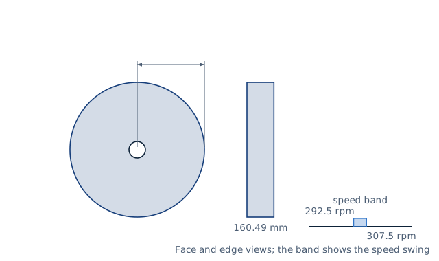
Drawn for the default inputs. It redraws as you change them.
Results are estimates. They do not replace the governing code, class or flag requirements, or a check by a competent person. Report a problem
Introduction
A flywheel stores energy as rotation, E = ½ I ω², and evens out machines whose torque comes in pulses: presses, punches, piston engines and compressors. It gives up energy when it slows and takes it back when it speeds up. A 50 kg·m² flywheel that slows from 315 to 285 rpm releases about 4.9 kJ.
This calculator works both ways. It gives the energy a flywheel stores and releases between two speeds, with the coefficient of speed fluctuation. Or, from the energy swing a machine needs and the speed fluctuation it can accept, it gives the moment of inertia, the mass of a solid disc or rim of chosen radius, the disc thickness, the rim speed and the centrifugal stress. It is for machine designers and students following Shigley chapter 16.
Formulas
E = ½ I ω²
ΔE = E₂ − E₁ = ½ I (ω₂² − ω₁²)
C_s = (ω₂ − ω₁) / ω,    ω = (ω₁ + ω₂) / 2
ΔE = C_s I ω²    so    I = ΔE / (C_s ω²)
Mass for a radius r, and stress at the mean speed (v = ω r):
solid disc:  m = 2 I / r²,   t = m / (ρ π r²),   σ_centre = (3 + ν)/8 · ρ v²
thin rim:    m = I / r²,     σ_hoop = ρ v²
I — moment of inertia; ω₁, ω₂ — lowest and highest speed in the cycle; ω — mean speed
ΔE — energy swing, the largest change of energy over a cycle from the torque–angle diagram
C_s — coefficient of speed fluctuation; ρ — density; ν = 0.3; t — disc thickness
Assumptions and limitations
The flywheel is rigid and turns about a fixed axis. The energy swing is an input; it comes from integrating the torque–angle diagram of the machine.
The mass ignores the hub, arms and shaft. For a rim this errs on the safe side, because the arms add inertia.
The stresses are elastic centrifugal stresses at the mean speed. Keyways, bolt holes and the overspeed case add to them and must be checked separately.
The disc is of uniform thickness. Webbed or tapered flywheels need their own inertia, which the mass moment of inertia calculator can give.
Worked example
A punch press needs 2 500 J from its flywheel during each stroke. The flywheel turns at a mean 300 rpm, and the speed may vary by 5 %, so C_s = 0.05. Size a solid steel disc of 400 mm radius.
Rim speed: 31.42 × 0.4 = 12.57 m/s; centre stress 0.4125 × 7 850 × 12.57² = 0.51 MPa, far below the strength of steel.
A rim of the same radius would need only half the mass, 317 kg, because all its mass sits at the outside.
The worked example, drawn by the same code as the live drawing above.
FAQ
How much energy does a flywheel store?
E = ½ I ω². A 50 kg·m² flywheel at 300 rpm stores 24.7 kJ, but only the difference between its highest and lowest speed is usable in each cycle.
What is the coefficient of speed fluctuation?
The speed range over a cycle divided by the mean speed. A smaller C_s means smoother running and a heavier flywheel.
Why is a rim better than a solid disc?
Inertia grows with the square of the radius. A rim puts its mass at the outside, so it gives the same inertia for half the mass of a disc.
How do I find the energy swing?
Plot the torque the machine needs against crank angle, subtract the mean torque, and integrate. The largest area between two crossings is the energy swing.
What limits the size of a flywheel?
The centrifugal stress, which grows with the square of the rim speed. Cast iron flywheels are limited to lower rim speeds than steel ones.
Does a bigger flywheel need a bigger motor?
No. The motor supplies the mean power; the flywheel only evens out the peaks. A larger flywheel takes longer to reach speed at start-up.
Before every release the calculator must reproduce each case below. The note under each case says where the expected answer comes from: a standard, a textbook, a published table, or a hand calculation shown in full.
Energy swing 2 500 J at 300 rpm, C_s 0.05: I = 2 500 / (0.05 × 31.416²) = 50.66 kg·m²; speeds 292.5 and 307.5 rpmShigley's Mechanical Engineering Design, 10th ed., eq. 16-62 (hand calculation)
50 kg·m² between 285 and 315 rpm: ΔE = ½ × 50 × (32.987² − 29.845²) = 4 934.8 J, C_s = 0.1Shigley eqs. 16-60 and 16-61 (hand calculation)
Mass and thickness: I 50.66 kg·m² as a 0.4 m solid steel disc is 633.3 kg and 160.5 mm thick; as a thin rim 316.6 kgSolid disc I = ½ m r², thin ring I = m r² (Meriam and Kraige, Dynamics; hand calculation)
Centrifugal stress at 12.566 m/s in steel: thin rim ρ v² = 1.2396 MPa; solid disc centre (3.3/8) ρ v² = 0.5113 MPaShigley 10th ed., §3-15 Stresses in rotating rings (ν = 0.3)
Energy scales with speed squared: doubling the speed band quadruples the energy at each speedE = ½ I ω²
Upper speed not above the lower, zero energy swing and C_s above 1.5 are rejectedBehaviour check: warnings and rejected inputs
Worked example of the article: the calculator reproduces 50.66 kg·m², 633 kg, 160.5 mm, 292.5 rpm, 307.5 rpm to the digits printedThe worked example on this page, to the digits printed
Assumptions and sources
Assumptions and limits
The flywheel is a rigid body on a fixed axis: E = ½ I ω². The energy it gives up or absorbs between two speeds is the difference of the kinetic energies (Shigley §16-12).
The coefficient of speed fluctuation is C_s = (ω₂ − ω₁)/ω with the mean speed ω = (ω₁ + ω₂)/2, so ΔE = C_s I ω² exactly. Typical design values are given by the machine type; the user chooses C_s.
The energy swing ΔE is the largest difference in the integrated torque–angle diagram over a cycle; this calculator takes it as an input.
Mass from inertia uses a uniform solid disc (I = ½ m r²) or a thin rim with all the mass at radius r (I = m r²); the inertia of the hub, arms and shaft is neglected, which errs on the safe side for a rim.
Stresses are elastic centrifugal stresses at the mean speed: ρ v² for a thin rim and (3 + ν)/8 ρ v² at the centre of a solid disc with ν = 0.3; they ignore keyways, bolt holes and overspeed, which the design must add.
Sources
Budynas and Nisbett, Shigley's Mechanical Engineering Design, 10th ed., §16-12 Flywheels, eqs. 16-59 to 16-62 (energy, coefficient of speed fluctuation)
Budynas and Nisbett, Shigley's Mechanical Engineering Design, 10th ed., §3-15 Stresses in rotating rings (solid disc and thin rim)
Meriam and Kraige, Engineering Mechanics: Dynamics, 8th ed., ch. 6 (kinetic energy of rotation, moments of inertia of a disc and a ring)
Cite this calculator
Papandreou, C. (2026). Flywheel energy calculator (inertia and speed fluctuation). Engineering Bible. https://engineeringbible.com/mechanical/flywheel-energy/
Embed this calculator on your site
Copy this HTML into your page. The calculator stays free to use and links back here.