Introduction
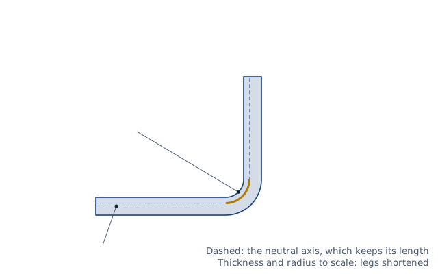
When sheet metal bends, the outside stretches and the inside compresses. One layer in between, the neutral axis, keeps its length. The bend allowance is the length of that layer through the bend. It sets how long the flat blank must be. A 90° bend in 2 mm steel over a 2 mm radius uses 4.16 mm of material along the neutral axis.
This calculator gives the bend allowance, the outside setback and the bend deduction of one bend. It then adds up the flat length of a part with any number of bends from its outside dimensions. It suggests a K-factor by DIN 6935 or takes your own. It is for sheet metal designers, press brake operators and anyone laying out a blank.
Formulas
One bend, with the bend angle θ in radians:
BA = θ × (R + K × T)
OSSB = tan(θ/2) × (R + T)
BD = 2 × OSSB − BA
Flat length from outside dimensions (legs measured to the mould lines):
L_flat = Σ legs − Σ BDK-factor suggested by DIN 6935:
k = 0.65 + 0.5 × log10(R/T)   for R/T < 5,   k = 1 above
K = k / 2- T — sheet thickness; R — inside bend radius; θ — bend angle (90° for an L)
- K — position of the neutral axis from the inside surface, as a fraction of T
- BA — bend allowance; OSSB — outside setback; BD — bend deduction
Assumptions and limitations
- The K-factor depends on the material, the tooling and the ratio R/T. The DIN formula gives 0.325 at R = T and 0.5 from R = 5T. A test bend and a measured blank give the best value for your shop.
- Leg lengths are outside dimensions. Each one runs to the point where the outside surfaces of two legs would meet.
- The bend angle is the angle the sheet turns through, not the angle left between the legs. A 90° L-bracket has a bend angle of 90°, and a 120° opening has a bend angle of 60°.
- In air bending, the inside radius follows the die opening, not the punch radius. Use the radius the part really gets.
- Springback and thinning in the bend are not modelled.
Worked example
A U-channel is 30 × 50 × 30 mm outside, in 2 mm steel, with a 2 mm inside radius. What blank length is needed?
- R/T = 1, so DIN 6935 gives k = 0.65 and K = 0.325.
- Bend allowance: π/2 × (2 + 0.325 × 2) = 4.16 mm.
- Outside setback: tan 45° × (2 + 2) = 4 mm.
- Bend deduction: 2 × 4 − 4.16 = 3.84 mm.
- Flat length: 30 + 50 + 30 − 2 × 3.84 = 102.33 mm.
With K = 0.44 the blank would be 103.05 mm, 0.72 mm longer.
Common cases
One 90° bend in common sheet and plate thicknesses, with the K-factor suggested by DIN 6935 from R/T. Subtract the bend deduction once per bend from the sum of the outside dimensions to get the blank length.
| Case | Thickness (mm) | Inside radius (mm) | K-factor | Bend allowance (mm) | Bend deduction (mm) |
|---|---|---|---|---|---|
| 0.8 mm sheet, inside radius 0.8 mm | 0.8 | 0.8 | 0.325 | 1.665 | 1.535 |
| 1 mm sheet, inside radius 1 mm | 1 | 1 | 0.325 | 2.0813 | 1.9187 |
| 1.5 mm sheet, inside radius 1.5 mm | 1.5 | 1.5 | 0.325 | 3.122 | 2.878 |
| 2 mm sheet, inside radius 2 mm | 2 | 2 | 0.325 | 4.1626 | 3.8374 |
| 2 mm sheet, inside radius 4 mm | 2 | 4 | 0.400 | 7.5406 | 4.4594 |
| 3 mm sheet, inside radius 3 mm | 3 | 3 | 0.325 | 6.2439 | 5.7561 |
| 4 mm plate, inside radius 6 mm | 4 | 6 | 0.369 | 11.743 | 8.2566 |
| 6 mm plate, inside radius 9 mm | 6 | 9 | 0.369 | 17.615 | 12.385 |
| 8 mm plate, inside radius 12 mm | 8 | 12 | 0.369 | 23.487 | 16.513 |
| 10 mm plate, inside radius 15 mm | 10 | 15 | 0.369 | 29.359 | 20.641 |
Every row is worked out by this calculator each time the site is built, and checked for impossible values. Open a case to load its inputs.
Common mistakes
- Entering the included angle as the bend angle. A drawing that shows 135° between the legs means a 45° bend. For the 30 × 50 × 30 mm channel of the example with two 45° bends the blank is 107.54 mm; entering 135° gives 83.86 mm, almost 24 mm short.
- Adding the bend allowance to outside dimensions. Bend allowance goes with the flat lengths inside the bends; bend deduction goes with the outside dimensions. Adding 2 × 4.16 mm to the 110 mm of outside legs in the example gives 118.33 mm instead of 102.33 mm.
- Using the punch radius in air bending. In air bending the inside radius follows the die opening, so the part may not get the punch radius. If the channel of the example really bends to 3 mm instead of 2 mm, the blank is 101.74 mm, not 102.33 mm, and a blank cut to the 2 mm figure makes the part about 0.6 mm oversize.
- One K-factor for every radius. The K-factor rises with R/T: DIN 6935 gives 0.325 at R = T, 0.400 at R = 2T and 0.5 from R = 5T. A fixed K = 0.44 makes the 2 mm channel blank 103.05 mm, 0.72 mm longer than the DIN value. Check it with a test bend.
- A flange shorter than the outside setback. A 2 mm sheet over a 2 mm radius has an outside setback of 4 mm, so a 3 mm leg has no flat left to bend against. The calculator warns about it; it often means the leg lengths were entered in the wrong units.
FAQ
What is bend allowance?
The length of the neutral axis through the bend. Add it to the straight flat parts of the legs to get the blank length.
What is the difference between bend allowance and bend deduction?
Bend allowance is added to the inside flat lengths. Bend deduction is subtracted from the outside dimensions. Both give the same blank.
What K-factor should I use?
Usually between 0.3 and 0.5. Small radii give lower values, large radii approach 0.5. The DIN 6935 formula and a test bend are the best starting points.
How do I find the K-factor from a test bend?
Bend a strip of known length, measure the legs, and work out the bend allowance that matches. Then solve BA = θ (R + K T) for K.
Is the bend angle the same as the included angle?
No. The bend angle is 180° minus the angle between the legs. A part that opens to 135° has a 45° bend.
How does the inside radius depend on the die?
In air bending, the inside radius is a fraction of the V-die opening, set by the material. Bottoming and coining press the radius of the punch into the part.
Related calculators
- Press tonnage calculator — press brake force for the bend.
- Tap drill calculator — holes for threaded fasteners in the part.
- Weld metal and filler calculator — welding the bent parts together.
- Steel and metal weight calculator — the weight of the blank.